The Motor Vehicle Mechanics ClipArt gallery offers 238 illustrations of motor vehicle mechanics, including circuit diagrams of numerous parts of cars made by several manufacturers.

This carburetor is a device that blends air and fuel for an internal combustion engine.

Carburetor

This carburetor is a device that blends air and fuel for an internal combustion engine.

An engine and spur-drive connections of a Stanley Steam Carriage.

Steam Carriage

An engine and spur-drive connections of a Stanley Steam Carriage.

An image showing the arrangement of a driving chain. It is similar to the chains used on bicycles.

Driving Chain

An image showing the arrangement of a driving chain. It is similar to the chains used on bicycles.

"Repair-link for round-link chain. A, section by a meridian plane; B, perspective elevation showing the completed link with both halves in place; C, top view of one half-section; D, top view of the other half-section, showing the break of the joint. The interrupted side is open wide enough to pass the stock of the solid link adjacent to the repair-link on either side." -Whitney, 1911

Repair Link of Chain

"Repair-link for round-link chain. A, section by a meridian plane; B, perspective elevation showing…

Chassis wiring diagram for the Gray & Davis starting and lighting installation on the Peerless, Model 56.

Chassis Wiring

Chassis wiring diagram for the Gray & Davis starting and lighting installation on the Peerless, Model…

An illustration of the Rolls Royce chassis with engine and axle viewed form the top. A chassis is the underneath frame and the gears in the car. The back axle is connected to the shaft coming from the engine.

Top View of Six Cylinder 1910 Rolls Royce Chassis with Engine and Axle

An illustration of the Rolls Royce chassis with engine and axle viewed form the top. A chassis is the…

Auto-lite battery cut-out.

Circuit Breaker

Auto-lite battery cut-out.

Diagram for testing short-circuits between windings.

Circuit Test

Diagram for testing short-circuits between windings.

A Hancock Coach cross-sectioned in order to display the engine and driving connections. (A) is the exhaust pipe that leads steam to screen (C) and up the flue (D) along with other exhaust from grate (B). (E) is the boiler, (H) is the out-take pipe, (K) is the engine cylinder, (J) is the water-feed pump, (G) is a rotary fan that creates forced drought, and (F) is the flue leading to the grate.

Hancock Coaches

A Hancock Coach cross-sectioned in order to display the engine and driving connections. (A) is the exhaust…

Roller contact timer.

Contact Timer

Roller contact timer.

Section of Splitdorf generator showing controller.

Controller

Section of Splitdorf generator showing controller.

Relation of ignition distributor to engine crankshaft.

Crankshaft

Relation of ignition distributor to engine crankshaft.

An AC motor is an electric motor that is driven by an alternating current. It consists of two basic parts, an outside stationary stator having coils supplied with alternating current to produce a rotating magnetic field, and an inside rotor attached to the output shaft that is given a torque by the rotating field. There are two types of AC motors, depending on the type of rotor used. The first is the synchronous motor, which rotates exactly at the supply frequency or a sub multiple of the supply frequency. The magnetic field on the rotor is either generated by current delivered through slip rings or by a permanent magnet.The second type is the induction motor, which turns slightly slower than the supply frequency. The magnetic field on the rotor of this motor is created by an induced current.

Current Motor

An AC motor is an electric motor that is driven by an alternating current. It consists of two basic…

Diagram of Delco Dynamotor for single-unit system.

Delco

Diagram of Delco Dynamotor for single-unit system.

Delco starting and lighting installation on the Auburn, Model 6-44.

Delco

Delco starting and lighting installation on the Auburn, Model 6-44.

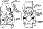
Delco starting and lighting installation on the Austin twelve-cylinder model.
Delco

Delco starting and lighting installation on the Austin twelve-cylinder model.

Details of brushes and brush switches, Delco Single-Unit System.

Delco

Details of brushes and brush switches, Delco Single-Unit System.

Section showing Delco Mercury-Bath voltage regulator.

Delco

Section showing Delco Mercury-Bath voltage regulator.

Delco starting and lighting installation on the Cole, Model 860.

Delco

Delco starting and lighting installation on the Cole, Model 860.

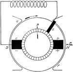
Delco starting and lighting installation on the Cole, Model 880.
Delco

Delco starting and lighting installation on the Cole, Model 880.

Delco third-brush regulator.

Delco

Delco third-brush regulator.

Delco starting and lighting installation on the Davis, models 6-H, 6-I, and 6-K.

Delco

Delco starting and lighting installation on the Davis, models 6-H, 6-I, and 6-K.

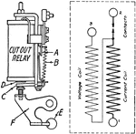
Delco starting and lighting installation on the Davis, models 6-J.
Delco

Delco starting and lighting installation on the Davis, models 6-J.

Sketch and diagram for Delco cut-out relay.

Delco

Sketch and diagram for Delco cut-out relay.

Delco starting and lighting installation on the Elgin, Model 6-E-16.

Delco

Delco starting and lighting installation on the Elgin, Model 6-E-16.

Delco starting and lighting installation on the Elkhart, 1917 model.

Delco

Delco starting and lighting installation on the Elkhart, 1917 model.

Wiring diagram for generator circuits of Delco installation on Cadillac 1912 model.

Delco

Wiring diagram for generator circuits of Delco installation on Cadillac 1912 model.

Wiring diagram of starting motor circuit for all Delco 6-24-volt systems.

Delco

Wiring diagram of starting motor circuit for all Delco 6-24-volt systems.

Wiring diagram for Delco System on Cadillac 1914 models.

Delco

Wiring diagram for Delco System on Cadillac 1914 models.

Wiring diagram for Delco System on Cadillac 1915 models.

Delco

Wiring diagram for Delco System on Cadillac 1915 models.

Wiring diagram for Delco installation on the Buick models C24 and C25.

Delco

Wiring diagram for Delco installation on the Buick models C24 and C25.

Wiring diagram for Delco installation on Buick models C36 and C37.

Delco

Wiring diagram for Delco installation on Buick models C36 and C37.

Wiring diagram for Delco installation on Buick 1916 models.

Delco

Wiring diagram for Delco installation on Buick 1916 models.

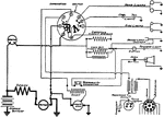
Delco starting and lighting installation on the Buick, models D-34-35.
Delco

Delco starting and lighting installation on the Buick, models D-34-35.

Generator of Delco two-unit system.

Delco

Generator of Delco two-unit system.

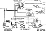
Delco starting and lighting installation on the Cadillac, model 53.
Delco

Delco starting and lighting installation on the Cadillac, model 53.

Delco starting and lighting installation on the Cadillac, model 55.
Delco

Delco starting and lighting installation on the Cadillac, model 55.

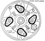
End view of Delco starting motor, showing commutator and brushes.
Delco

End view of Delco starting motor, showing commutator and brushes.

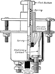
Part section of Delco starting switch.

Delco

Part section of Delco starting switch.

Complete wiring diagram of Delco system on 1917 and 1918 Westcott cars.

Delco

Complete wiring diagram of Delco system on 1917 and 1918 Westcott cars.

Front and reverse face of combination switch for Delco two-unit system.

Delco

Front and reverse face of combination switch for Delco two-unit system.

Delco ignition installation on the Haynes, models 40, 40-R, 41.

Delco

Delco ignition installation on the Haynes, models 40, 40-R, 41.

Delco starting and lighting installation on the Hudson, 1917 Super-Six.
Delco

Delco starting and lighting installation on the Hudson, 1917 Super-Six.

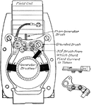
Diagram showing method of adjusting third brush in 1916 Delco generator.

Delco

Diagram showing method of adjusting third brush in 1916 Delco generator.

Delco starting and lighting installation on the Kissel, 1917 Twelve-Cylinder Model.

Delco

Delco starting and lighting installation on the Kissel, 1917 Twelve-Cylinder Model.

Delco starting and lighting installation on the Liberty, 1917 model.

Delco

Delco starting and lighting installation on the Liberty, 1917 model.

Delco starting and lighting installation on the Moon, Model 6-43.

Delco Installation

Delco starting and lighting installation on the Moon, Model 6-43.

Delco starting and lighting installation on the Moon, Model 6-66.

Delco Installation

Delco starting and lighting installation on the Moon, Model 6-66.

Motor VehiclesDelco starting and lighting installation on the Nash, Model 681.

Delco Installation

Motor VehiclesDelco starting and lighting installation on the Nash, Model 681.

Delco ignition installation on National Twelve-Cylinder cars, series A-K.

Delco Installation

Delco ignition installation on National Twelve-Cylinder cars, series A-K.

Delco starting and lighting installation on the Oakland 1917 cars, Model 32-B.

Delco Installation

Delco starting and lighting installation on the Oakland 1917 cars, Model 32-B.

Delco starting and lighting installation on the Oakland, Model 34.

Delco Installation

Delco starting and lighting installation on the Oakland, Model 34.

Delco starting and lighting installation on the Olds 1917 cars, model 45.

Delco Installation

Delco starting and lighting installation on the Olds 1917 cars, model 45.

Delco starting and lighting installation on the Olds, 1917 cars, model 45A.

Delco Installation

Delco starting and lighting installation on the Olds, 1917 cars, model 45A.

Delco starting and lighting installation on the Pathfinder, 1917 Twelve-Cylinder Model.

Delco Installation

Delco starting and lighting installation on the Pathfinder, 1917 Twelve-Cylinder Model.

Delco starting and lighting installation on the Pilot 1917 cars, model 6-45.

Delco Installation

Delco starting and lighting installation on the Pilot 1917 cars, model 6-45.

Delco starting and lighting installation on the Premier 1917 cars, model 6-B.

Delco Installation

Delco starting and lighting installation on the Premier 1917 cars, model 6-B.

Delco starting and lighting installation on the Stephens, 1917 model.

Delco Installation

Delco starting and lighting installation on the Stephens, 1917 model.

A Worm and sector steering device, cross-sectioned. It was developed by Panhard-Levassor. The spindle of the steering wheel carries a worm gear at the base of the head.

Steering Device

A Worm and sector steering device, cross-sectioned. It was developed by Panhard-Levassor. The spindle…

Two types of steering devices. The image on the left is a combined nut and rack steering gear. It is resistant to backlash and has almost perfect irreversibility. The image on the right is a typical irreversible steering device with a spirally grooved gear plate operating a sector.

Steering Devices

Two types of steering devices. The image on the left is a combined nut and rack steering gear. It is…