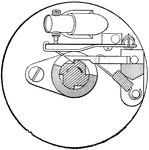
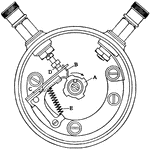
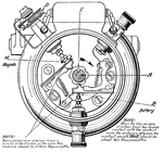
The Motor Vehicle Mechanics ClipArt gallery offers 238 illustrations of motor vehicle mechanics, including circuit diagrams of numerous parts of cars made by several manufacturers.

A universal joint differential. The sprocket is used to twist the sleeve that is holding the gear in place. As long as the travel is straight, the pinions don't move on their axes. When an axis is turned however, rotation begins, which causes the two big wheels of the wagon to move.

Joint Differential

A universal joint differential. The sprocket is used to twist the sleeve that is holding the gear in…

End elevation and section of Dixie 4-Cylinder Magneto showing construction and connections.

Dixie 4-Cylinder Magneto

End elevation and section of Dixie 4-Cylinder Magneto showing construction and connections.
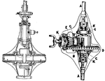
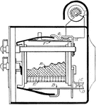
A diagram that shows the details and housing of a Dixie Interrupter.

Dixie Interrupter

A diagram that shows the details and housing of a Dixie Interrupter.

Bevel drives of two different early model cars. (A) and (B) are the sleeves and cases for axles and gears, (D) is the driving gear, (E) is the driving pinion, (G) is a ball bearing on (E), (H H) are universal couplings on the differential, (K) are adjustments, and (L) is a yoke of a flexible driving shaft.

Bevel Drive

Bevel drives of two different early model cars. (A) and (B) are the sleeves and cases for axles and…
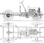
A sectional view of an early model car showing a propeller shaft drive through bevel gears to the rear axle.

Propeller-Shaft Drive

A sectional view of an early model car showing a propeller shaft drive through bevel gears to the rear…

Section of Gray and Davis Lighting Dynamo.

Dynamo

Section of Gray and Davis Lighting Dynamo.

Mounting and drive of Northeast Dynamotor.

Dynamotor

Mounting and drive of Northeast Dynamotor.

Sectional view showing details of Dyneto regulator-cut-out.

Dyneto

Sectional view showing details of Dyneto regulator-cut-out.

Dyneto starting and lighting installation on the Franklin, Series 8.

Dyneto

Dyneto starting and lighting installation on the Franklin, Series 8.

Dyneto starting and lighting installation on the Franklin, Series 9.

Dyneto

Dyneto starting and lighting installation on the Franklin, Series 9.

Connections for Dyneto regulator cut-out.

Dyneto

Connections for Dyneto regulator cut-out.

Starting-motor circuit for Dyneto system.

Dyneto

Starting-motor circuit for Dyneto system.

Generator circuit for Dyneto system.

Dyneto

Generator circuit for Dyneto system.

Wiring diagram for Dyneto one-wire system.

Dyneto One-Wire

Wiring diagram for Dyneto one-wire system.

Wiring diagram for Dyneto two-wire system.

Dyneto Two-Wire

Wiring diagram for Dyneto two-wire system.

Mechanism of Apollo Electric Horn.

Electric Horn

Mechanism of Apollo Electric Horn.

Electrical diagram for Gray & Davis starting and lighting installation on the Peerless, Model 56.

Electrical Diagram

Electrical diagram for Gray & Davis starting and lighting installation on the Peerless, Model 56.
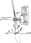
A propellor engine illustrating of the motion of the propellor when in flight.

Aeroplane Engine

A propellor engine illustrating of the motion of the propellor when in flight.

A six cylinder Rolls Royce engine viewed from the carburetor side. The carburetor is used to mix air and fuel in the engine.

Carburetor Side View of Six Cylinder Rolls Royce Engine

A six cylinder Rolls Royce engine viewed from the carburetor side. The carburetor is used to mix air…

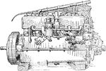
A valve side view of the six cylinder Rolls Royce engine, showing the location of the magneto. The magneto is used to ignite fuel in the engine at a high voltage by using a spark plug's gap.

Valve Side View of Six Cylinder Rolls Royce Engine

A valve side view of the six cylinder Rolls Royce engine, showing the location of the magneto. The magneto…
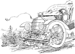
A guard over each wheel of a motor vehicle, for example, that is shaped and positioned so as to block the splashing of water or mud.

Vehicle Fender

A guard over each wheel of a motor vehicle, for example, that is shaped and positioned so as to block…
A type of overcurrent protection device.

Fuse

A type of overcurrent protection device.

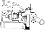
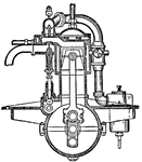
Internal-combustion engine, side view.

Gas Engine, Internal-Combustion Engine

Internal-combustion engine, side view.

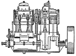
Internal-combustion engine (sectional view)

Gas Engine, Internal-Combustion Engine

Internal-combustion engine (sectional view)

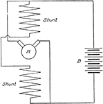
Connections Bosch-Rushmore generator.

Generator

Connections Bosch-Rushmore generator.

Auto-lite generator of the bipolar type.

Generator

Auto-lite generator of the bipolar type.

Diagrammatic section of four-pole auto-lite generator.

Generator

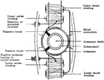
Diagrammatic section of four-pole auto-lite generator.

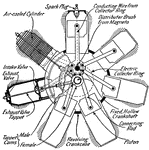
This illustration shows a Gnome motor with revolving cylinders and its many parts: Spark Plug; Conducting Wire from Collector Ring; Distributor Brush from Magneto; Electric Collector Ring; Fixed, Hollow Crankshaft; Connecting Rod; Piston; Revolving Crankcase; Tappet Cams (male and female); Exhaust Valve Tappet; Exhaust Valve; Intake Valve; Air-Cooled Cylinder. Gnome was the leading type of air cooled motor in the 1920s.

Gnome Motor, with Revolving Cylinders

This illustration shows a Gnome motor with revolving cylinders and its many parts: Spark Plug; Conducting…

Gray & Davis starting and lighting installation on the Chandler 1917 light-weight six.

Gray and Davis

Gray & Davis starting and lighting installation on the Chandler 1917 light-weight six.

Gray & Davis starting and lighting installation on the Chandler 1917 light-weight six.

Gray and Davis

Gray & Davis starting and lighting installation on the Chandler 1917 light-weight six.

Diagram of layout for testing Gray & Davis generator.

Gray and Davis

Diagram of layout for testing Gray & Davis generator.

Wiring diagram for Gray & Davis dynamo and regulator.

Gray and Davis

Wiring diagram for Gray & Davis dynamo and regulator.

A section of Gray & Davis generator for silent-chain drive.

Gray and Davis Generator

A section of Gray & Davis generator for silent-chain drive.

Section of Gray & Davis generator with ignition distributor gearing (shaft drive).

Gray and Davis Generator

Section of Gray & Davis generator with ignition distributor gearing (shaft drive).

Gray & Davis starting motor with reduction gearing for open flywheel. 1-Motor Pinion; 2-Intermediate Gear; 5-Intermediate Shaft; 6-Sliding Pinion; 7-Shifter Fork; 8-Shifter Rod; 10-Clevis; 12-Switch Rod; 23, 24, and 25-Oilers; 26-Oil Plug.

Gray and Davis Motor

Gray & Davis starting motor with reduction gearing for open flywheel. 1-Motor Pinion; 2-Intermediate…
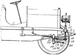
Diagram for locating grounded fields.

Grounded Fields

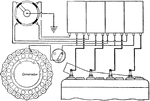
Diagram for locating grounded fields.

Section of Hall double headlight.

Headlight

Section of Hall double headlight.

A light with a reflector and lens mounted on the front of a locomotive, automobile, or other vehicle. Also called headlamp.

Automobile Headlight

A light with a reflector and lens mounted on the front of a locomotive, automobile, or other vehicle.…

A headlamp is a lamp, usually attached to the front of a vehicle such as a car.

Dirigible Headlight

A headlamp is a lamp, usually attached to the front of a vehicle such as a car.

A headlamp is a lamp, usually attached to the front of a vehicle such as a car, with the purpose of illuminating the road ahead during periods of low visibility, such as darkness precipitation. Headlamp performance has steadily improved throughout the automobile age, spurred by the great disparity between daytime and night time traffic fatalities.

Vehicle Headlight

A headlamp is a lamp, usually attached to the front of a vehicle such as a car, with the purpose of…

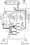
Wiring diagram of series control for dimming headlights.

Headlights

Wiring diagram of series control for dimming headlights.

Diagram of a high-tension ignition system. A is the source of current, usually a batter in earlier days, as indicated by the conventional sign, placed in a primary circuit that also includes the contact maker C, the primary winding of the coil B, and the vibrator G.

High-Tension Ignition System

Diagram of a high-tension ignition system. A is the source of current, usually a batter in earlier days,…

Wiring diagram of non-vibrator high-tension system.

High-Tension System

Wiring diagram of non-vibrator high-tension system.

A Clubbe and Southey Pivoted Steering Hub. The hub is the part that makes up the turning apparatus for a steering wheel.

Steering Hub

A Clubbe and Southey Pivoted Steering Hub. The hub is the part that makes up the turning apparatus for…

Auto-lite ignition, starting, and lighting system on Briscoe 1917 motor cars.

Ignition

Auto-lite ignition, starting, and lighting system on Briscoe 1917 motor cars.

Method of "Crowning" the spring, Delco Ignition Relay.

Ignition Relay

Method of "Crowning" the spring, Delco Ignition Relay.

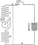
Diagram of a low-tension ignition system. A is the battery, B is a spark coil, and C, D, and E are the elements of a make-and-break device that is mechanically actuated at regular intervals by the motor itself to produce the sparks within the cylinder.

Ignition System

Diagram of a low-tension ignition system. A is the battery, B is a spark coil, and C, D, and E are the…

Four-cylinder low-tension ignition system.

Ignition System

Four-cylinder low-tension ignition system.

A diagram showing hydraulic analogy of ignition system.

Ignition System

A diagram showing hydraulic analogy of ignition system.

Wiring diagram of the Bosch Duplex Ignition System.

Ignition System

Wiring diagram of the Bosch Duplex Ignition System.

Wiring diagram of the Ford Ignition System.

Ignition System

Wiring diagram of the Ford Ignition System.

A wiring diagram for Connecticut Ignition System.

Ignition System

A wiring diagram for Connecticut Ignition System.

Essentials of battery ignition system.

Ignition System

Essentials of battery ignition system.

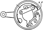
Atwater-Kent Interrupter.

Interrupter

Atwater-Kent Interrupter.

Delco magneto type interrupter.

Interrupter

Delco magneto type interrupter.

Diagram of earlier model of Delco Interrupter.

Interrupter

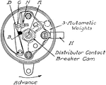
Diagram of earlier model of Delco Interrupter.

Wiring diagram for Bijur two-wire system on the Jeffery Chesterfield Six (1916 model).

Jeffery Chesterfield Six

Wiring diagram for Bijur two-wire system on the Jeffery Chesterfield Six (1916 model).

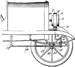
A patented device from the turn of the twentieth century. It is used for driving on all four wheels by using universal joints. The steering arms aren't inclined, so the wheels are able to follow their paths without slipping

Universal Joints

A patented device from the turn of the twentieth century. It is used for driving on all four wheels…
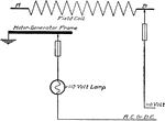
Wiring diagram showing method of using lamp-testing set for locating grounds.

Lamp Testing

Wiring diagram showing method of using lamp-testing set for locating grounds.