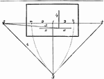
This figure comprises the whole of the points and lines preparatory to beginning a drawing in "angular perspective." 1) The point of sight; 2)The horizontal line; 3) The point of station; 4) The nearest corner of the object to be drawn; 5) The ground line of the building or object, lying on that side, and produced from the nearest corner up to the horizontal line, in order to determine the vanishing point marked 5; 6) A line taken from the vanishing point 5, to the point of station 3; 7) A line drawn at right angles to 6, and extending from the point of station to the horizontal line, at its junction with which the vanishing point, marked 8, is determined; 9) A point of measurement obtained by the use of the vanishing point 8; 10) The other point of measurement, obtained by vanishing point 5; 11) The geometrical scale of the building or object upon a base line drawn through the nearest corner.

Angular Perspective

This figure comprises the whole of the points and lines preparatory to beginning a drawing in "angular…

The perspective in this plate is "angular perspective," and the figure it represents is a flat square surface; its dimensions are supposed to be either twenty feet or twenty inches. 1) Two lines drawn from the nearest corner of theboard, to the horizontal line, and at a distance from each other equal to the thickness of the board; this fixes the vanishing point at 1. 2) A line drawn from the above vanishing point to the point of station. 3) A line taken at right angles to 2, from the point of station, and fixing on the horizontal line the position of the vanishing point 3. 4) Two lines drawn from the nearest corner of the board to the vanishing point 3, similarly to the previously drawn lines 1. 5) One point of measurement, obtained in the usual way, by the distance of 3 from the point of station. 6) The point of measurement. 7) The line of the geometrical scale, being a line drawn across the base of the nearest corner, and marked according to scale, twenty feet or twenty inches. 8,8) Lines taken from either end of the geometrical scale towards the point of measurement, but extending no farther than where they meet the lines 1,1, and 4,4. 9,10) Small perpendicular lines drawn at the above intersections, by which the width of the board is ascertained. 11) The side of the board opposite and really parallel to that marked 4, and therefore tending to the same vanishing point. 12) The back of the board, opposite and parallel to the front marked 1, and consequently tending to the same vanishing point. The lines 1,1; 4,4; 11 and 12, being strongly marked, the figure will be completed.

Angular Perspective

The perspective in this plate is "angular perspective," and the figure it represents is a flat square…

This object is a cube, having therefore all its faces of equal dimensions; and as both sides recede, "angular perspective" is employed. The point of sight, horizontal line, and point of station, having been fixed upon, the line A is first to be drawn, touching the bottom of the nearest corner, and is for the geometrical scale or height of the cube, which, in this instance, will be called twelve feet; that is, twelve feet must be marked on the scale from the corner on either side. 1) The ground line of the square, taken from the centre of the geometrical scale line to the horizontal line; by its junction with which is determined the vanishing point or that side. 2) A line drawn from the above vanishing point to the point of station. 3) A line drawn at right angles at the point of station to the line 2, as far as the horizontal line, its intersection with which will give the correct vanishing point to the other side. 4) The ground line of the cube running to the last vanishing point. 5) The nearest corner of the cube, twelve feet in height, being equal to the width. The points of measurement are next to be ascertained, and to be marked in the usual way; and the lines B drawn from the ends of the geometrical scale towards the point of measurement give the perspective width or depth of both sides. This is found at their cutting of the ground lines 1 and 4. The line 6 represents the top line of one side of the cube, and runs from the nearest corner to the vanishing point. 7) The other top line; and it is drawn to the other vanishing point. 8) The far corner line raised vertically from the crossing of the lines B and 1. 9) The other corner line raised vertically from the intersection of the lines B and 4. The lines 1, 4, 5, 6, 7, 8, 9, being strengthened, the figure is complete.

Angular Perspective

This object is a cube, having therefore all its faces of equal dimensions; and as both sides recede,…

This cube has four additional cubes of equal dimensions. This is effected by first drawing the cube in the order and then finding the centre of the upright line 5, that being the nearest corner line of this first cube. The centre being found at 10, take the line 10 to the vanishing point for that side of the cube; this will give the centres of all the other upright lines of that side of all the added cubes. The line 11 is drawn from the top of the corner line 5, through the intersection of 8 and 10, until it meets the ground line 1, at its junction with which the upright line is raised for the far corner line 12 of the second cube. The three other cubes are described precisely in the same manner, being found by the diagonal lines traversing each pair of the cubes, through the intersection of the centre line 10, with each perpendicular line raised from the meeting of the previous diagonal line with the ground line 1. It will be perceived that a further distance of twelve feet is added to one side of the geometrical scale, and marked A. This is done merely to prove the correctness of the first diagonal line 11, passing through the centre line 10, to determine the perspective depth of the second cube. For if a line be taken from the end of the geometrical scale A to the point of measurement on the horizontal line, it will be found to meet the ground line 1 at exactly the same point; thus proving the truth of both modes of drawing. The former mode, however, is more convenient where a number of cubes are to be drawn; as the geometrical scale might extend far beyond the limits of the paper, and consequently give much more trouble.

Angular Perspective

This cube has four additional cubes of equal dimensions. This is effected by first drawing the cube…

This figure differs from the others because they are solid cubes. Further, the geometrical scale is used for the two cubes, because, being only two, it will be found in this way that fewer lines will be necessary, leaving the figure less intricate and confused. The two frnt sides of the cubes are produced in the same way as far as line 10, which is the farthest corner line of the second cube. 11) The line is drawn from the extremity of 10 to the vanishing point of 7, the two lines being really parallel. 12) Is drawn from the top of 9 to the vanishing point of line 6, these also being parallel. 13) Is drawn from the top of the upright centre line 8, to the vanishing point of 11 and 7, these being all really parallel to each other. 14) Is the far ground line taken from the lower extremity of 9 to the vanishing point of 1, these lines being also parallel. 15 and 16) Are lines drawn from the corner end of 10 and 8 to the vanishing point of 4, the three lines being really parallel. 17 and 18) Are upright lines raised at the intersection of the lines 16 and 15, with the ground line 14, being the far corners of the cubes; they respectively will meet the intersections of lines 11 and 13 with 12. These lines will complete the figure.

Angular Perspective

This figure differs from the others because they are solid cubes. Further, the geometrical scale is…
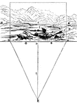
"A landscape is supposed to be viewed from the spot marked E; and that the spectator is desirous of representing on the plane of his paper a certain portion of the scene as seen by him fom this point. That portion constitutes his real picture. The distance of this picture,- or distance of the eye from the plane of the picture (which is the same thing), -means the distance intervening between the spectator's position, and that point on the ground directly in front of him, where the picture, which he is about to make, ought properly to commence. Upon the choice of a proper and judicious distance the beauty of his work will in a great measure depend. Suppose the landscape to be viewed from the point E, then that portion of the scene which the eye can easily take in, without moving the head, and without the slightest strain upon the optic nerve, will constitute the picture from that point. Now, under this condition the spectator will find that he does not distinctly see the ground immediately before him, but that he obtains a perfectly easy view of it only at some distance from his position at E. It is the space included between the point E (where he is placed), and the supposed point alluded to, and here marked S, that establishes the required distance of the picture, that is, the distance of the eye from the proposed picture. For instance, let S be that point on the ground immediately in front of the eye, and if through S a straight line be supposed to be drawn, perpendicular to the distance ES, this line will pass through and determine the foremost objects of the proposed picture, and therefore at this line the picture must commence."

Distance

"A landscape is supposed to be viewed from the spot marked E; and that the spectator is desirous of…
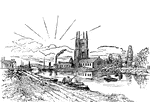
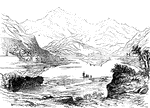
A drawing of a landscape positioning a horizontal line.

Horizontal Line

A drawing of a landscape positioning a horizontal line.

A landscape illustration demonstrating proper positioning of a horizontal line.

Horizontal Line

A landscape illustration demonstrating proper positioning of a horizontal line.

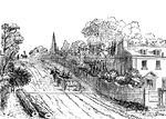
A drawing of a landscape showing the proper position for the horizontal line.

Horizontal Line

A drawing of a landscape showing the proper position for the horizontal line.

Illustration depicting horizontal landscape.

Horizontal Line

Illustration depicting horizontal landscape.

A landscape drawing showing the proper position for the horizontal line.

Horizontal Line

A landscape drawing showing the proper position for the horizontal line.

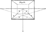
The perspective shown in this plate is parallel perspective; and the subject here intended to be represented is a flat and perfectly square surface, such as the floor of a room, a chess board, or any other such object.  1) The front edge of the given square; 2) One side of it receding to the vanishing point, which also is the point of sight; 3) The other side receding to the same point; 4) A line taken from one corner of the front edge, to the point of measuremen on the opposite side, and giving the perspective width or depth of the square at the intersection of the line 3; 5) A line drawn at the above intersection, and parallel to the front edge; this will give the back of the square. The lines 1, 2, 3, and 5 may then be strongly marked, and the figure will be thus completed. 6) This line is taken from the corner of the front edge to the opposite point of the measurement, showing how exactly either this line, o that marked 4, will give the perspective width of the square. It serves also to find the centre.

Parallel Perspective

The perspective shown in this plate is parallel perspective; and the subject here intended to be represented…
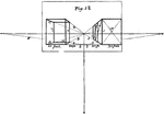
Two upright oblong figures are here represented in parallel perspective. They may be imagined to resemble the sides and fronts of houses, or their blank walls. One of the figures has two others attached to it of equal dimensions; and these additions might be similarly multiplied to any extent, by the numbers, 7, 8, 9 and 10, in the followig rules. 1) Lines forming to complete fronts of two separate and detached oblongs. 2) The geometrical scale at the base, marked twenty feet. 3) The ground lines of the fronts running to the vanishing point. 4) The top lines tending to vanishing point. 5) Lines from the geometrical scale, to the points of measurement, determining the perspective depths of the oblongs. 6) Perpendicular lines raised at the intersection of the lines 3 and 5, and giving the farthest upright corner lines of the oblongs. The two figures will thus be completed. The remaining lines inserted in the figure are intended to give two other oblongs (or rather their retiring sides) attached to the first, and supposed to be of the same dimensions. They are determined first by finding the centre 7 of the near corner line 1. From 7 a line is drawn to the vanishing point. A line marked 8 is then drawn from the near extremity of 1 through 6, where it is cut by 7; at its intersection with the bottom line 3, the perpendicular line 9 is raised, and another oblong front is completed. A line 10 is drawn, and determined as the line 8 was, from the top of 6, and by crossing the lines 7 and 3. The lines 13, 14, and 15, are inserted merely to show the inner side and back of the other oblong, as they would be seen were the object made of glass. Thus 13,13 are lines for the top and bottom of the back; formed by drawing them to the vanishing point; 14,14 are the top and bottom lines of the farthest side, found by straight lines being drawn from both ends of , until they meet 13,13; at which point of meeting the upright corner of the oblong are completed.

Parallel Perspective

Two upright oblong figures are here represented in parallel perspective. They may be imagined to resemble…

That an accurate notion of the vertical line may be obtained, the plane of the picture must be supposed to be perpendicular to the horizontal plane. If a straight line be drawn from the spectator's eye, perpendicular to this plane of the picture, that line will fall upon the plane at a point in the horizontal line directly opposite to the eye. This point, C, is called the centre of the picture, or centre of view. In reference to the eye of the spectator, every straight line perpendicular to the plane of the picture appears to converge towards this point or centre. The line which, drawn from the eye of the spectator, determines this centre C, is called the vertical line. It is a straight line through S, perpendicular to the horizontal line, and the base of the picture; and is represented by the line EC.

Vertical Line

That an accurate notion of the vertical line may be obtained, the plane of the picture must be supposed…