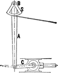
A pulley system used to reduce motion between the piston and the indicator of the steam engine. The indicator is attached by a string on the curved bottom triangle. As the piston moves, the string is pulled to record the pressure of the steam.

Reducing Motion of Piston and Indicator using Brumbo Pulley

A pulley system used to reduce motion between the piston and the indicator of the steam engine. The…
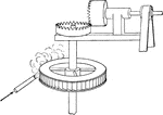
An illustration of a rotary steam engine. The steam turbine system was invented by Branca in 1629. Steam spins the turbine to turn a series of gears, generating power.

Steam Rotary Engine

An illustration of a rotary steam engine. The steam turbine system was invented by Branca in 1629. Steam…

A De Laval steam turbine connected to a generator. The turbine generates electricity by turning the shaft. The turbine is operates by providing steam into the vanes.

De Laval Steam Turbine Connected to Generator

A De Laval steam turbine connected to a generator. The turbine generates electricity by turning the…

A cross sectional view of the Pearsons turbine for generating electricity. The turbines, located in P are turned by steam, generating electricity.

Pearsons Turbine for Electricity Generator

A cross sectional view of the Pearsons turbine for generating electricity. The turbines, located in…
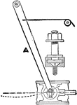
A reducing lever for large engines to measure pressure of steam in the cylinder. The string to the indicator is pulled as the piston compresses the steam. Similarly, the string is pulled as the steam is expanded.

Reducing Lever for Piston and Indicator in Large Steam Engines

A reducing lever for large engines to measure pressure of steam in the cylinder. The string to the indicator…
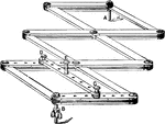
"It is placed horizontally with the pivot, B, resting on a support opposite the crosshead when in mid—position. If the pivot B is adjusted to the proper height and at the right distance from the cross head, the cord from the indicator may be attached to the pin E without any pulleys."—Derr, 1911

Horizontal Pivot Pantograph for Motion Reduction between Piston and Steam Engine Indicator

"It is placed horizontally with the pivot, B, resting on a support opposite the crosshead when in mid—position.…
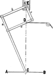
A pantograph used to reduce motion of the piston. At point D, a string is attached to the indicator, measuring pressure of steam in cylinder. The pantograph is attached to a solid surface on top. As the piston moves, the pantograph pulls the string.

Motion Reduction using Pantograph of Piston Connected to Indicator of Steam Engine

A pantograph used to reduce motion of the piston. At point D, a string is attached to the indicator,…

"The cylinder covers are also made hollow to permit a circulation of live steam. A cylinder having the annular space (A) filled with steam is said to be jacketed. A liner, L, is often used in jacketed cylinders." —Derr, 1911

Jacketing Piston to Reduce Heat Loss

"The cylinder covers are also made hollow to permit a circulation of live steam. A cylinder having the…
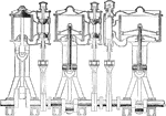
A piston diagram from a triple expansion steam engine. The three cylinders are designed at high, medium, and low pressures, with receiver between each cylinders. This design divides work between the three piston to increase efficiency.

Piston of a Triple Expansion Steam Engine

A piston diagram from a triple expansion steam engine. The three cylinders are designed at high, medium,…
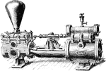
"The direct—acting steam pump has the steam piston at one end of a rod and the water position at the other end. The steam pressure acts directly on the piston; no fly light, and there is no revolving mass to carry by the dead points." —Derr, 1911

Direct Acting Steam Pump

"The direct—acting steam pump has the steam piston at one end of a rod and the water position…

"As the eccentric turns in the strap, the point O moves in the dotted circle around O', and the point A also moves in a circle. When half a revolution is accomplished the point O will be at O", the Point A will be at A", and the eccentric strap and valve rod will be in the position indicated by the dotted lines." —Derr, 1911

Shaft in an Eccentric Motion from Steam Engine

"As the eccentric turns in the strap, the point O moves in the dotted circle around O', and the point…

Illustration of a cross compound steam engine. The engine is designed to hold pressure until the engine's minimum pressure is achieved.

Cross Compound Steam Engine

Illustration of a cross compound steam engine. The engine is designed to hold pressure until the engine's…
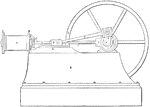
A low power steam engine. The piston inside cylinder A moves the wheel, generating power at 100 horsepower or less. The steam from the system escapes the from the piston, moving the wheel.

Low Power Simple Steam Engine Diagram

A low power steam engine. The piston inside cylinder A moves the wheel, generating power at 100 horsepower…

A low power simple expansion steam engine. The steam engine can run at 100 horsepower, and not run continuously. The as the piston in the cylinder expands, part of steam is exhausted into the surrounding. The piston then moves the wheel to generate power.

Low Power Simple Expansion Steam Engine

A low power simple expansion steam engine. The steam engine can run at 100 horsepower, and not run continuously.…
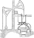
An illustration of Newcomen atmospheric steam engine. The boiler heats the water to build up steam in the piston. While the steam lever closes, the water is let in, and the piston compresses the steam to generate energy. The compressed steam turns to liquid, and opens the steam valve.

Newcomen Atmospheric Steam Engine

An illustration of Newcomen atmospheric steam engine. The boiler heats the water to build up steam in…
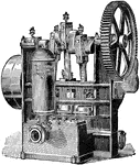
A power pump steam engine without shaft. The engine turns the wheel with the reciprocal motion of the piston.

Power Pump Steam Engine

A power pump steam engine without shaft. The engine turns the wheel with the reciprocal motion of the…
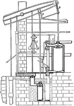
The illustration showing Watt's final steam engine design. The engine is fitted with series of rods to guide the in a straight line. James Watt and William Murdoch invented the throttle valve, centrifugal valve, regulator, and slide valve to improve on the steam engine.

Watt's Final Steam Engine Design

The illustration showing Watt's final steam engine design. The engine is fitted with series of rods…
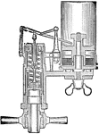
"The indicator consists of a cylinder in which a piston is fitted, a spring, multiplying lever, and parallel motion for the pencil and cylinder or drum for the paper. The piston is fitted accurately to the cylinder and has a travel about one—half inch." —Derr, 1911

Thompson Indicator for Steam Engine

"The indicator consists of a cylinder in which a piston is fitted, a spring, multiplying lever, and…
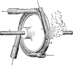
A De Laval steam turbine. The turbine is operated by supplying steam into the four nozzles. The steam is then expanded and exits the valve through the vanes.

De Laval Steam Turbine

A De Laval steam turbine. The turbine is operated by supplying steam into the four nozzles. The steam…
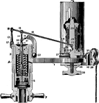
"If only one indicator is to be used for both ends of the cylinder, it may be connected by side pipes and a three way (pipe valve). By this method both diagrams are taken on the same card and with the loss but one revolution." —Derr, 1911

Three Way Pipe Valve for Attaching One Steam Engine Indicator

"If only one indicator is to be used for both ends of the cylinder, it may be connected by side pipes…