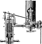
"If only one indicator is to be used for both ends of the cylinder, it may be connected by side pipes and a three way (pipe valve). By this method both diagrams are taken on the same card and with the loss but one revolution." —Derr, 1911

Three Way Pipe Valve for Attaching One Steam Engine Indicator

"If only one indicator is to be used for both ends of the cylinder, it may be connected by side pipes…
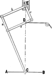
A pantograph used to reduce motion of the piston. At point D, a string is attached to the indicator, measuring pressure of steam in cylinder. The pantograph is attached to a solid surface on top. As the piston moves, the pantograph pulls the string.

Motion Reduction using Pantograph of Piston Connected to Indicator of Steam Engine

A pantograph used to reduce motion of the piston. At point D, a string is attached to the indicator,…
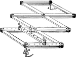
"It is placed horizontally with the pivot, B, resting on a support opposite the crosshead when in mid—position. If the pivot B is adjusted to the proper height and at the right distance from the cross head, the cord from the indicator may be attached to the pin E without any pulleys."—Derr, 1911

Horizontal Pivot Pantograph for Motion Reduction between Piston and Steam Engine Indicator

"It is placed horizontally with the pivot, B, resting on a support opposite the crosshead when in mid—position.…
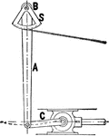
A pulley system used to reduce motion between the piston and the indicator of the steam engine. The indicator is attached by a string on the curved bottom triangle. As the piston moves, the string is pulled to record the pressure of the steam.

Reducing Motion of Piston and Indicator using Brumbo Pulley

A pulley system used to reduce motion between the piston and the indicator of the steam engine. The…
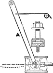
A reducing lever for large engines to measure pressure of steam in the cylinder. The string to the indicator is pulled as the piston compresses the steam. Similarly, the string is pulled as the steam is expanded.

Reducing Lever for Piston and Indicator in Large Steam Engines

A reducing lever for large engines to measure pressure of steam in the cylinder. The string to the indicator…

"The spring balance, B, is shown in a horizontal position. The ropes are held to the pulley or fly—wheel face by blocks of wood, O. The weights at W may be replaced by a spring balance if desired." —Derr, 1911

Rope Brake Measuring Brake Horse Power

"The spring balance, B, is shown in a horizontal position. The ropes are held to the pulley or fly—wheel…

"As the eccentric turns in the strap, the point O moves in the dotted circle around O', and the point A also moves in a circle. When half a revolution is accomplished the point O will be at O", the Point A will be at A", and the eccentric strap and valve rod will be in the position indicated by the dotted lines." —Derr, 1911

Shaft in an Eccentric Motion from Steam Engine

"As the eccentric turns in the strap, the point O moves in the dotted circle around O', and the point…

"The amount that the valve overlaps the steam ports is called the lap of the valve. It will at once be seen that both the admission and exhaust ports may remain closed during a part of the stroke, thus making expansion and compression possible." —Derr, 1911

Slide Valve of Steam Engine

"The amount that the valve overlaps the steam ports is called the lap of the valve. It will at once…

"The maximum displacement of the valve is attained when the eccentric is horizontal. In this position both the steam and exhaust ports are wide open, and any further motion motion of the piston will cause the valve to move toward its mid position." —Derr, 1911

Valve with Lap of Steam Engine Where Steam Enters the Slide Valve Compartment

"The maximum displacement of the valve is attained when the eccentric is horizontal. In this position…

"Since the valve must move a distance equal to the outside lap before admission can take place, it is evident that the eccentric can no longer be at right angles to the crank at the beginning of the stroke, but must be ahead of the right—angle point by an amount equal to AOC." —Derr, 1911

Valve with Lap of Steam Engine at Extreme Left with Exhaust Ports Open

"Since the valve must move a distance equal to the outside lap before admission can take place, it is…

"While the crank is moving from the position, steam is being admitted to the head end and being exhausted from the crank end. The inside lap being less than the outside lap, causes the exhaust to continue longer than the admission." —Derr, 1911

Steam Engine Valve with Lap Where Steam is Admitted to the Slide Valve

"While the crank is moving from the position, steam is being admitted to the head end and being exhausted…

"The relative positions of crank, eccentric and valve when the exhaust closes on the crank end and compression begins. Between these two positions the steam is expanding in the head end and exhausting from the crank end." —Derr, 1911

Steam Engine Valve with Lap Steam Where Slide Valve is Closed

"The relative positions of crank, eccentric and valve when the exhaust closes on the crank end and compression…

"If the inside lap is increased, the valve must move farther before released occurs and the crank angle would be greater than illustrated. On the return of the valve to the dotted position, the port will close earlier and make an earlier compression. Decreasing inside lap will cause earlier release and later compression." —Derr, 1911

Steam Engine Valve with Lap Steam Where Slide Valve Moved to Open Position

"If the inside lap is increased, the valve must move farther before released occurs and the crank angle…

An illustration of the valve with lap at the end of the crank end steam compression. The piston will restart the compression cycle of at the head of the piston. As the piston moves, the sliding valve in the top compartment will fill with steam and closes.

Steam Engine Valve with Lap Steam Where Slide Valve is in Open Position

An illustration of the valve with lap at the end of the crank end steam compression. The piston will…

"This occurs in horizontal engines when the valve is set on top of the cylinder instead of on one side. By means of the rocker AG the valve may receive its proper motion." —Derr, 1911

Steam Engine Valve with Lap Connected to Rocker

"This occurs in horizontal engines when the valve is set on top of the cylinder instead of on one side.…

"It is usual to put the engine on center before setting the valve. First put the engine in a position where the piston has nearly completed the outward stroke, and make a mark M on the guide opposite the corner of the crosshead or at some convenient place." —Derr, 1911

Steam Engine Valve Centered with Piston

"It is usual to put the engine on center before setting the valve. First put the engine in a position…
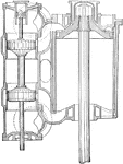
"This valve consists of two pistons connected by a sleeve through which the valve rod passes. This valve rod is prolonged to a small balancing piston, placed directly over the main valve." —Derr, 1911

Cross Sectional View of the High Pressure Cylinder of Piston Valve from USS Massachusetts

"This valve consists of two pistons connected by a sleeve through which the valve rod passes. This valve…

"When set full gear forward, the valve admits steam to the crank end of the cylinder, and the crank revolves as shown by the arrow. As the crank turns, both eccentrics impart motion to the link, but the "go ahead" link pin H approximately coincides with the link block." —Derr, 1911

Eccentric Motion of the Steam Engine Crank in Full Gear

"When set full gear forward, the valve admits steam to the crank end of the cylinder, and the crank…

"This arrangement makes it possible to place the valve and steam chest above the valve motion. A rod from the bell crank lever on the reverse shaft E, leads back to the engineer's cab and connects with the reverse lever." —Derr, 1911

Steam Engine Rocker Arrangement with Valve and Reverse Rod in Eccentric Motion

"This arrangement makes it possible to place the valve and steam chest above the valve motion. A rod…

"As the speed increases, and the link is 'notched up', the lead is increased as the cut—off is shortened, and at high speed we have a large lead. With the Gooch link, the lead can be set for average running speed, and although a little too great for good work at slow speed." —Derr, 1911

Steam Engine Gooch Link and Valve Gear Arrangement

"As the speed increases, and the link is 'notched up', the lead is increased as the cut—off is…
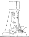
An outline of the Marshall gear from a steam engine. The piston rotates the crank shaft at point H around axis S. The rod F is connected to the bottom rod E. Rod F rotates at axis P to rotate the engine backwards and forward.

Outline of a Steam Engine Marshall Gear Reducing Friction and Wear

An outline of the Marshall gear from a steam engine. The piston rotates the crank shaft at point H around…

A Joy valve gear for steam engine rotating the wheel in the direction of the arrow. The lever F changes the direction the wheel would turn when turned to point B.

Joy Steam Engine Valve Gear Rotating Wheel

A Joy valve gear for steam engine rotating the wheel in the direction of the arrow. The lever F changes…

An illustration of the steam engine with Walschaert gear system on rail tracks. The piston moves the long shaft connected to the wheel. The lever adjusts the rods on top up and the lower ones down to rotate the wheels opposite from the arrows.

Steam Engine with Walschaert Gear on Railroad

An illustration of the steam engine with Walschaert gear system on rail tracks. The piston moves the…
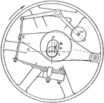
"All fly—wheel governors operate by shifting the eccentric either to change the angular advance, the travel of the valve, or both. The principle of a governor arranged to give decreasing lead under the head of governors." —Derr, 1911

Top View of the Fly Wheel Governor Turning Clockwise

"All fly—wheel governors operate by shifting the eccentric either to change the angular advance,…

"The main valve controls admission, release, and compression; the other (valve) regulates the cut—off only, which may be changed without in any way affecting the other events of the stroke. This cut—off valve may be placed in a separate valve chest, or it may be placed in the back of the main valve." —Derr, 1911

Close up View of Double Sliding Valve Gears from Steam Engine

"The main valve controls admission, release, and compression; the other (valve) regulates the cut—off…

"An eccentric on the main shaft gives an oscillating motion to a circular disc called the wrist plate, pivoted at the center of the cylinder. It transmits motion to each of the four valves through adjustable links known as steam rods or exhaust rods, according to whether they move the admission or exhaust valves." —Derr, 1911

Steam Engine with Reynolds Corliss Gear

"An eccentric on the main shaft gives an oscillating motion to a circular disc called the wrist plate,…

"The steam arm is keyed to the valve spindle which passes loosely through a bracket on which the bell—crank lever turns, and the spindle is packed to make a steam—tight joint where it enters the cylinder. Motion of the steam rod toward the right will turn the bell—crank lever and raise the hook stud." —Derr, 1911

Close up of Reynolds Corliss Gear from Steam Engine

"The steam arm is keyed to the valve spindle which passes loosely through a bracket on which the bell—crank…
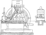
An illustration of a Corliss steam engine to generate 5000 kW of electricity. The turbines to create electricity is located on the right hand side and the large circular casing in the left. The steam enters the system at a high pressure to turn the turbines.

5000 kW Corliss and Curtis Steam Engine for Electric Generation

An illustration of a Corliss steam engine to generate 5000 kW of electricity. The turbines to create…
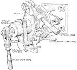
"The governor cam rod operates a plate cam having a curved slot so shaped that it takes place of both the knock—off and the safety cam. The steam arm is keyed to the valve spindle and carries at its lower end a steel die which is free to slip up and down a small amount." —Derr, 1911

Steam Engine Brown Releasing Gear

"The governor cam rod operates a plate cam having a curved slot so shaped that it takes place of both…
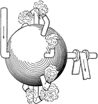
A simple steam turbine by Hero of Alexandra during first century AD. The turbine consists of a hollow sphere and pipes. Steam enters the hollow ball, and exits at the pipe around the equator. This then turns the sphere turbine.

Hero's Simple Steam Turbine

A simple steam turbine by Hero of Alexandra during first century AD. The turbine consists of a hollow…
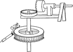
"In 1629, Branca, an Italian, invented a turbine much like a miniature water wheel, which was driven by a jet of steam from a nozzle directed against the buckets of the wheel. This is the simplest form of an impulse turbine." —Derr, 1911

Branca's Impulse Steam Turbine

"In 1629, Branca, an Italian, invented a turbine much like a miniature water wheel, which was driven…
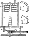
"A compound turbine was patented by Real and Pichon, the idea being to reduce the velocity of rotating passing the seam through successive wheels G, separated by disks B B containing outlets C to permit the passage of the steam from one chamber to another. H is one of the blades, F the shaft, and M the steam exhaust." —Derr, 1911

Real and Pichon Compound Steam Turbine

"A compound turbine was patented by Real and Pichon, the idea being to reduce the velocity of rotating…

"A view of Wilson's invention is shown; a, b, and c, are vance which are attached to and rotate with the drum D, while d, e, and f are stationary guide vanes. Steam enters at the left, passes through the turbine longitudinally, and exhausts at the right." —Derr, 1911

Wilson's Compound Steam Turbine

"A view of Wilson's invention is shown; a, b, and c, are vance which are attached to and rotate with…

"In 1858, Hartman Bros. patented a turbine consisting of two revolving disks c and c' fixed to a shaft D. Between them was a segment of stationary reversing blades d d. Steam entered from a nozzle F and was exhausted at H; G is the casing." —Derr, 1911

Hartman's Compound Impulse Turbine

"In 1858, Hartman Bros. patented a turbine consisting of two revolving disks c and c' fixed to a shaft…

"In 1885, Parsons took out his first turbine patent on a motor along the lines previously suggested by Wilson, and is responsible for the successful development of this type of motor. His first turbine, took steam in the center A, and exhausted at both ends through the exhaust passage E E, thus avoiding any end—thrust on the shaft B." —Derr, 1911

Early Parsons Steam Turbine

"In 1885, Parsons took out his first turbine patent on a motor along the lines previously suggested…
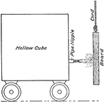
"Suppose a hollow cube to be filled with some fluid (water or steam) at a given pressure, and to have an opening in one side that can readily be closed. The arrangement is such that when the outlet is opened, the internal pressure will remain the same. If the outlet is opened, the fluid will rush out, and if the jet is supposed to strike against a board free to move, the jet will exert a force upon the board tending to swing it in the direction of the jet." —Derr, 1911

Apparatus for Measuring Jet Stream of Steam

"Suppose a hollow cube to be filled with some fluid (water or steam) at a given pressure, and to have…

"If the velocity of impact of the jet is V feet per second, its velocity in the same direction after striking the plate will be zero, a definite force will be exerted on that plate, equal to the force necessary to impart a velocity of V feet in one second to the mass of water in the jet." —Derr, 1911

Water Jet Deflected 90 Degrees Measuring Force

"If the velocity of impact of the jet is V feet per second, its velocity in the same direction after…
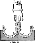
"Now if the plate were shaped as shown, so that the direction of the jet were completely reversed turned through 180 degrees, there would be an additional pressure on the plate, due to the reaction of the jet leaving it. This, neglecting friction, would be equal to the original impulse, thus making the total force on plate 2 F instead of F. It is quite evident that if the force is twice as great, the work must be double." —Derr, 1911

Force Measurement by Deflecting Water Jet 180 Degrees

"Now if the plate were shaped as shown, so that the direction of the jet were completely reversed turned…
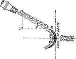
"If a jet with the velocity V strikes the bucket at an angle a, its velocity A B could be resolved into two components —one C B at right angles to the shaft, and one C A parallel to the shaft. The one at right angles to the shaft, commonly known as the velocity of whirl, would produce a rotative impulse equal to Vcosa, and V1, the velocity of the vane necessary for maximum efficiency." —Derr, 1911

Jet Steam Stream Hitting Curved Vane

"If a jet with the velocity V strikes the bucket at an angle a, its velocity A B could be resolved into…
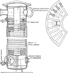
"The accumulator may consist of a large tank in which are numerous plates over which water can flow, or may contain simply water rapidly circulated by artificial means. As the exhaust steam from the engine enters this accumulator, it spreads out over the exposed water surface, and some of it is condensed if there is an excess of pressure due to more steam being supplied by the exhaust than is being utilized by the turbine." —Derr, 1911

Interior View of Rateau Accumulator

"The accumulator may consist of a large tank in which are numerous plates over which water can flow,…

"Turbines require very much smaller foundations than reciprocating engines reciprocating engines of the same power, and these foundations will therefore cost very much less. It is hard to get a direct comparison between turbines and reciprocating engines as a class, because the foundations for high—speed reciprocating engines will not be as massive as for the heavier, low—speed engines." —Derr, 1911

Westinghouse Turbo Steam Engine Generator Plan

"Turbines require very much smaller foundations than reciprocating engines reciprocating engines of…
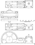
"By placing the condensers underneath the turbine, as is frequently done at the present time, not only may a considerable amount of floor space be saved, but the turbine can more readily exhaust into the condenser. As we have already seen, at high vacuum the volume of steam is very large, and the exhaust pipe from the turbine will be proportionally large." —Derr, 1911

Corliss Steam Engine Generator Plan

"By placing the condensers underneath the turbine, as is frequently done at the present time, not only…

"The bearings are of the plain ring—oiling type, usually provided with water jackets. The shaft not being unduly long, there is little danger of whipping, and the speeds of rotation not being very high, special precautions are not necessary. Sometimes the turbines are supported by three bearings, the high and intermediate states being separated from the low by a third bearing." —Derr, 1911

DeLaval Steam Electric Generator

"The bearings are of the plain ring—oiling type, usually provided with water jackets. The shaft…

A cross sectional view of Rateau electric generator turbine by Western Electric Company. Steam is used to turn the turbine to generate electricity. The turbine rotates at 1500 revolutions per minute and operates at 1500 horsepower.

Cross Section View of Rateau Turbine Electric Generator by Western Electric Company

A cross sectional view of Rateau electric generator turbine by Western Electric Company. Steam is used…

"The Zoelly turbine has been developed rather extensively abroad, and is being manufactured largely through a syndicate of builders including some American firms. It is a turbine essentially of the Rateau type, a multi—pressure—stage turbine, but it has fewer stages, usually not over ten for condensing and five for non—condensing." —Derr, 1911

Zoelly Condensing Turbine Electric Generator

"The Zoelly turbine has been developed rather extensively abroad, and is being manufactured largely…

"The shaft, where it passes through the diaphragm, is fitted to a bronze bushing with a few thousandths of an inch clearance. This bushing seats on the metal surface of the diaphragm with latitude for slight side motion. It is kept to its seat by the steam pressure, but can move sideways to accommodate any whipping motion of the shaft." —Derr, 1911

Sectional View of Kerr Turbine

"The shaft, where it passes through the diaphragm, is fitted to a bronze bushing with a few thousandths…

An illustration of 9000 kilowatts capacity vertical Curtis turbine. Each turbines are located between the stationary nozzles. The steam enters from the steam chest into the moving gears, then to stationary blades. Electricity is then generated at the movable blades.

9000 Kilowatts Vertical Curtis Turbine

An illustration of 9000 kilowatts capacity vertical Curtis turbine. Each turbines are located between…

"The marine turbine of this type (Curtis turbine) installed in the U.S. Cruiser Salem had seven pressure stages with four velocity steps in the first stage, and three in each of the others. Steam passes from the steam chest through the nozzles, each of which may be closed by a valve operated from the governor. The number open at any one time depends upon the load." —Derr, 1911

Cross Sectional View of U.S.S Salem Steam Engine Showing Curtis Turbines

"The marine turbine of this type (Curtis turbine) installed in the U.S. Cruiser Salem had seven pressure…
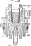
"The upper bearing with dowel—pins and key fit into corresponding dowel holes and key—way in the bottom of the shaft, and rotate with it. When the oil is supplied to the bearing, under a high pressure, it fills the central circular space between the blocks and forces them slightly apart. The oil then escapes between the annular edges of these two blocks and is collected into a drain and returned to the original supply." —Derr, 1911

Cross Sectional View of Curtis Turbine Step Bearing

"The upper bearing with dowel—pins and key fit into corresponding dowel holes and key—way…

A cross sectional view of a four stage vertical Riedler—Stumpf turbine. The steam enters and exit, indicated by the arrows. The steam spins a series of turbines located in the middle at a high pressure. As the turbine spins, the shaft, located in the middle, produces useable energy.

Cross Sectional View of Four Stage Vertical Riedler Stumpf Turbine

A cross sectional view of a four stage vertical Riedler—Stumpf turbine. The steam enters and exit,…
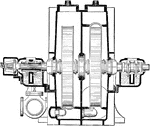
A two stage condensing Terry turbine from a steam engine. The steam, entering from the top, rotates the two turbines in the casing to generate electricity.

Cross Sectional View of Two Stage Condensing Terry Steam Engine Turbine

A two stage condensing Terry turbine from a steam engine. The steam, entering from the top, rotates…

"Steam enters at E and gradually expands in volume until it exhausts at G. The rotor is usually built in three different diameters to facilitate mechanical construction and to avoid excessively small and excessively large vanes. It is thus possible to use a large number of vanes of the same size." —Derr, 1911

Cross Sectional View of Parsons Turbine

"Steam enters at E and gradually expands in volume until it exhausts at G. The rotor is usually built…

A cross sectional view of Westinghouse Parsons turbine. Steam enters at V and exits at E, turning the turbines, R. The turbines turns the shaft, B, to produce energy to produce electricity. During this process, the steam, at high pressure, is expanded to a lower pressure.

Westinghouse Parsons Turbine Viewed Cross Sectionally

A cross sectional view of Westinghouse Parsons turbine. Steam enters at V and exits at E, turning the…
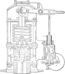
"In the Curtis turbine, steam is admitted through a series of valves, the number of which depends upon the capacity of the machine. The valves are arranged to open successively, two—thirds of them being open at full load. The action of the valves is so regulated that they are either fully open or fully closed. Any increasing load is taken care of by the opening of an additional valve, this valve closing when the load falls off." —Derr, 1911

Sectional View of Governor for Varying Number of Nozzles Opened

"In the Curtis turbine, steam is admitted through a series of valves, the number of which depends upon…
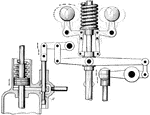
"An admission of steam occurs about once in every thirty revolutions at approximately full load. The pilot valve is continually oscillating, thus preventing any liability of sticking, but its period of oscillation is varied directly by the governor. Steam, therefore, enters the turbine in puffs, the duration of which depends upon the load; at slight overloads the valve would be constantly open." —Derr, 1911

Turbine Governor for Varying Time of Admission

"An admission of steam occurs about once in every thirty revolutions at approximately full load. The…
A heating device consisting of a series of connected pipes, typically inside an upright metal structure, through which steam or hot water is circulated so as to radiate heat into the surrounding space.

Device Radiator

A heating device consisting of a series of connected pipes, typically inside an upright metal structure,…
Any of various machines having a rotor, usually with vanes or blades, driven by the pressure, momentum, or reactive thrust of a moving fluid, as steam, water, hot gases, or air, either occurring in the form of free jets or as a fluid passing through and entirely filling a housing around the rotor.

Water Turbine

Any of various machines having a rotor, usually with vanes or blades, driven by the pressure, momentum,…
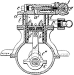
External-combustion engine in which heat is used to raise steam which either turns a turbine or forces a piston to move up and down in a cylinder

Steam Engine

External-combustion engine in which heat is used to raise steam which either turns a turbine or forces…
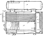
A heating unit designed to heat by boiling water, producing steam, and circulating it to radiators or steam baseboard units throughout the home.

Steam Boiler

A heating unit designed to heat by boiling water, producing steam, and circulating it to radiators or…
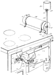
Used to convert water into steam from heat produced in a nuclear reactor core. They are used in pressurized water reactors between the primary and secondary coolant loops.

Steam Generator

Used to convert water into steam from heat produced in a nuclear reactor core. They are used in pressurized…