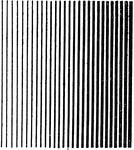
An exercise in creating a line shading, where the line is becoming thicker. The pen is slightly changed throughout the drawing.

Line Shading Light to Dark Tint

An exercise in creating a line shading, where the line is becoming thicker. The pen is slightly changed…
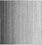
An illustration of creating a line shading from dark to light. The lines are gradually become thin. The pen is slightly changed throughout the drawing.

Line Shading Dark to Light Tint

An illustration of creating a line shading from dark to light. The lines are gradually become thin.…

"Illustrating the rule that an inclined illuminated surface is lightest nearest the eye and an inclined surface in shade is darkest nearest the eye." —French, 1911

Line Shading Application

"Illustrating the rule that an inclined illuminated surface is lightest nearest the eye and an inclined…

An example of the cylinder shaded by lines. The area without lines are where the light hit the cylinder. The line become darker when it is away from the light source.

Cylinder Line Shading

An example of the cylinder shaded by lines. The area without lines are where the light hit the cylinder.…

"A row of cylinders of different sizes. The effect of polish is given by leaving several brilliant lines, as might occur if light came in through several windows." —French, 1911

Series of Cylinder Line Shading

"A row of cylinders of different sizes. The effect of polish is given by leaving several brilliant lines,…

"A conical surface may be shaded by driving a fine needle at the apex and swinging a triangle about it, as in (A). To avoid a blot at the apex of a complete cone the needle may be driven on the extension of the side as in (B), or it may be shaded by parallel line as in (C)." —French, 1911

Different Cone Shading

"A conical surface may be shaded by driving a fine needle at the apex and swinging a triangle about…
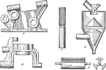
An application of line shading for curved surfaces used in mechanical drawing. The surfaces are shaded by using the cone shading technique.

Shaded Single Curved Surfaces

An application of line shading for curved surfaces used in mechanical drawing. The surfaces are shaded…
A line shading for spheres by guessing how the surface would look when shaded.

Sphere Shading

A line shading for spheres by guessing how the surface would look when shaded.

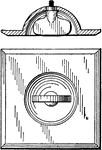
An application of shading using double curved surfaces of a screw in the socket.

Screw Shading

An application of shading using double curved surfaces of a screw in the socket.

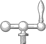
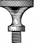
A thumb screw shading illustrating a double curved surface line shading technique.

Thumb Screw Shading

A thumb screw shading illustrating a double curved surface line shading technique.

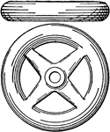
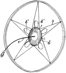
Shading wheel using lines by estimating how the light hit the surface.

Wheel Shading

Shading wheel using lines by estimating how the light hit the surface.

An application of shading double curved surface of a lever.

Lever Shading

An application of shading double curved surface of a lever.

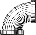
Line shading of a pipe using double curved surface technique.

Piper Shading

Line shading of a pipe using double curved surface technique.

A device used to transfer drawing onto opaque paper using bright tin, two showcase lamps, and plate glass. The drawings can be copied in pencil on heavy paper or Bistrol—board.

Transparent Drawing Board

A device used to transfer drawing onto opaque paper using bright tin, two showcase lamps, and plate…
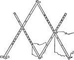
A simple pantograph used to reducing or enlarging images by using a pivot while drawing the larger image.

Pantograph

A simple pantograph used to reducing or enlarging images by using a pivot while drawing the larger image.

An illustration of a suspended pantograph has metal arms to resize images accurately in engineering work.

Suspended Pantograph

An illustration of a suspended pantograph has metal arms to resize images accurately in engineering…

An illustration of enlarging an image by using squares. This proportion method is done by using squares to resize the image.

Enlargement of Image by Squares

An illustration of enlarging an image by using squares. This proportion method is done by using squares…

T—squares can be temporarily adjusted by putting the thumb tack in the head as illustrated. This is used when the previous work does not align with the T-square.

Temporary Adjustment T-square

T—squares can be temporarily adjusted by putting the thumb tack in the head as illustrated. This…
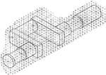
This is a simple child's toy, Toys are usually associated with children and pets.

Child's Hoop Toy

This is a simple child's toy, Toys are usually associated with children and pets.

An illustration of an isometric sketch to show a three dimensional object. The sketch is useful in elevation drawing, plans, and laying out curve diagrams.

Isometric Sketch

An illustration of an isometric sketch to show a three dimensional object. The sketch is useful in elevation…
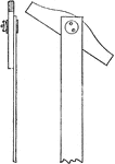
"Where the head is movable, the pivot should be quit large, and the hole in which it plays be bushed with metal; the washers must be large, and the clamp screws of hard metal, with deep threads and unreliable." —Grimshaw, 1902

Taper Head Adjustable T Square Side and Front View

"Where the head is movable, the pivot should be quit large, and the hole in which it plays be bushed…

A front and side view of a t square with rectangular head. The t square is used draw straight lines using the blade in mechanical drawing.

Fixed Rectangular Head T Square

A front and side view of a t square with rectangular head. The t square is used draw straight lines…
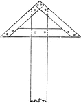
"To enable the drawing of long parallel, the head must have been a long contact surface with the edge of the board. It must also be wide enough to hold the blade stiffly." —Grimshaw, 1902

Fixed Triangular Head T Square

"To enable the drawing of long parallel, the head must have been a long contact surface with the edge…
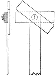
"Where the square has a fast and a loose head, the blade should be mortised into the fixed one and the nut and thumb screw arranged as shown; the movable swivel head being used the least." —Grimshaw, 1902

Adjustable Rectangular Head T Square

"Where the square has a fast and a loose head, the blade should be mortised into the fixed one and the…
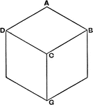
An illustration of Axonometric Projection, or object related by plane of projection, of a cube. The cube is drawn by having the cube resting on one side, then projecting each horizontal and vertical lines from A.

Axonometric Projection of a Cube

An illustration of Axonometric Projection, or object related by plane of projection, of a cube. The…
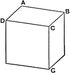
"The axes or edges, CG and CD, are foreshortened a like amount, while CB is foreshortened twice that of the other two. The angles of these axes being known and the reduced scale due to the foreshortening being given, the making of the projection is very simple." —Anthony, 1904

Axonometric Projection of a Rectangular Cube

"The axes or edges, CG and CD, are foreshortened a like amount, while CB is foreshortened twice that…
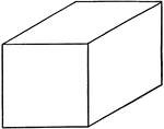
A rectangular cube drawn by using oblique projection. The original cube was projected parallel at a certain angle. The cube was drawn by drawing the front square in the front, then projecting it in an angle while connecting the edges.

Oblique Projection of a Rectangular Cube

A rectangular cube drawn by using oblique projection. The original cube was projected parallel at a…
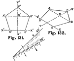
"DE being chosen as an isometric line or axis, a second axis, YY, is drawn isometrically perpendicular to it. Points C and F lie on this axis, and their position is readily determined, since measurements may be made on this line. As line AB, drawn through C, is an isometric line, points A and B may be located at their proper distances to the right and left of the axis YY." —Anthony, 1904

Pentagon Elevation and Projection Scaling

"DE being chosen as an isometric line or axis, a second axis, YY, is drawn isometrically perpendicular…

The illustration of constructing a circle or ellipse using isometric drawing. The inscribed circle is transferred to the top part of the cube by creating diagonal lines through the center and series of squares.

Isometric Drawing of Circle using Square

The illustration of constructing a circle or ellipse using isometric drawing. The inscribed circle is…
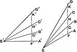
The illustration showing angles of 15, 30, and 45 degrees at angles 45 and 30 degrees. Measurement of angles is created by drawing at point E at 45 or 30 degrees, then draw a straight line from E to estimate the desired angle.

Measuring Angles in Isometric Planes

The illustration showing angles of 15, 30, and 45 degrees at angles 45 and 30 degrees. Measurement of…

The illustration of the side view of the oblique timber inserted into the horizontal timber. The drawing is done by drawing the square base, then draw an angled parallel line from the base.

Side View of Oblique Timber Framed in to Horizontal Timber

The illustration of the side view of the oblique timber inserted into the horizontal timber. The drawing…

A isometric drawing of the oblique and horizontal wood combined together. The image is drawn by creating the squared cube base, then, at the desired angle, draw the 3D view of the wood sticking up.

Isometric View of Oblique Timber Framed in to Horizontal Timber

A isometric drawing of the oblique and horizontal wood combined together. The image is drawn by creating…

The illustration of an irregular curves for solid. The isometric projection of the curve can be drawn by the series of perpendicular lines parallel to the axis.

Drawing Irregular Isometric Curves of Solid

The illustration of an irregular curves for solid. The isometric projection of the curve can be drawn…

A rolled out, or development, of the cylinder. The development is created by drawing the top curve with the dashed line where the folds are.

Development of Cylinder

A rolled out, or development, of the cylinder. The development is created by drawing the top curve with…

A development, or rolled out, cone where the point A is the meeting point for the sides. The development is drawn by drawing the arc by using a compass.

Development of Cone

A development, or rolled out, cone where the point A is the meeting point for the sides. The development…
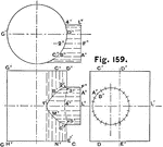
An illustration of two intersecting cylinders viewed from the side, top, and side of the intersecting cylinder. The intersecting cylinder drawing in mechanical and engineering drawings to show either a tank or pipes.

Three Views of Two Intersecting Cylinder

An illustration of two intersecting cylinders viewed from the side, top, and side of the intersecting…
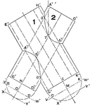
Auxiliary planes of two intersecting cylinder is drawn by drawing the first cylinder. Revolve the first cylinder onto itself to create two intersections.

Drawing Auxiliary Planes of Two Intersecting Cylinder

Auxiliary planes of two intersecting cylinder is drawn by drawing the first cylinder. Revolve the first…
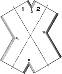
A sliced view at point VW, shown in the top figure. The inside view of the cylinders shows the points where the cylinders are connected.

Sliced View of Auxiliary Planes of Two Intersecting Cylinder

A sliced view at point VW, shown in the top figure. The inside view of the cylinders shows the points…
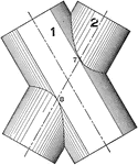
An outside view of two cylinders intersecting in an auxiliary plane. The dotted lines is the center of each cylinders.

Outside View of Auxiliary Planes of Two Intersecting Cylinder

An outside view of two cylinders intersecting in an auxiliary plane. The dotted lines is the center…
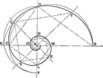
"If B and C are points in the spiral and the ratio of AC to AB be given, the intermediate point D may be obtained by describing a semicircle on BC as a diameter and erecting a perpendicular at A." —Anthony, 1904

Drawing Equiangular or Logarithmic Spiral

"If B and C are points in the spiral and the ratio of AC to AB be given, the intermediate point D may…

"This class of spirals may be generated by unwinding a perfectly flexible but inextensible chord from a polygon of any number of sides, the names of the involutes being derived from the polygons which determine their form. The curves consist of radii increasing by an amount equal to the length of the sides." —Anthony, 1904

Involute Spiral

"This class of spirals may be generated by unwinding a perfectly flexible but inextensible chord from…
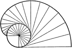
A helix spiral generated by revolving about an axis at an angle less than 90 degrees. This generates a cylindrical or coned shape as the tip meets.

Helix Spiral

A helix spiral generated by revolving about an axis at an angle less than 90 degrees. This generates…
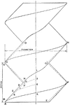
The illustration detailing of a screw thread. Threads are created by drawing a cylindrical shape at a constant diameter. The pitch, length between the threads, is drawn along the cylinder at an angle.

Drawing Screw Thread

The illustration detailing of a screw thread. Threads are created by drawing a cylindrical shape at…
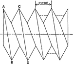
An illustration of the V thread screw. The screw is drawn by connecting the two opposite points of the thread to create the required pitch.

Conventional V Thread Screw

An illustration of the V thread screw. The screw is drawn by connecting the two opposite points of the…
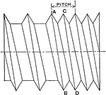
A double thread screw drawn by drawing diagonal lines in between the pitch. The double thread screw is a screw with threads bunched together between the pitch.

Double Thread Screw

A double thread screw drawn by drawing diagonal lines in between the pitch. The double thread screw…
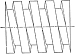
A close up of a square thread on a screw. This representation shows the correct an accurate three dimensional view of the screw.

Square Thread Screw

A close up of a square thread on a screw. This representation shows the correct an accurate three dimensional…
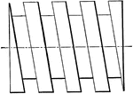
Illustration of a common representation for square thread screw. The screw is drawn in two dimensions and used in drafting plans and mechanical drawing.

Square Thread Screw Mechanical Drawing Representation

Illustration of a common representation for square thread screw. The screw is drawn in two dimensions…

A representation of the square threaded nut and screw. The left image shows the threaded screw with a continuous helix drawn. The nut is cut in half to show how the threads are drawn with respect to the screw.

Diagram of Square Thread Nut and Screw

A representation of the square threaded nut and screw. The left image shows the threaded screw with…
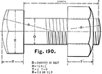
An illustration of the hexagonal bolt head showing measurements. The measurement of diameter, D, is used to calculate the dimensions. The diameter of the head and the nut, H, is 1 ½D ₌ ⅛, and the distance of T is half the diameter.

U.S. Standard Hexagonal Bolt Head

An illustration of the hexagonal bolt head showing measurements. The measurement of diameter, D, is…

A screw head with detailed measurements for accurate drawing. These measurements are based off the diameter of the overall screw and the head.

Diagram of Screw Head

A screw head with detailed measurements for accurate drawing. These measurements are based off the diameter…
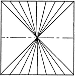
An exercise problem to create a vanishing point using lines. The line is drawn by placing a dot into the middle of the paper, then draw the lines angled into the middle. This creates an illusion that the lines are continuing for a long distance.

Vanishing Point Using Lines

An exercise problem to create a vanishing point using lines. The line is drawn by placing a dot into…
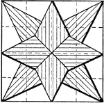
An illustration of drawing an eight point star using a series of pentagons to create a star. The paper is divided into a squares to use as a guide for drawing pentagons.

Constructing Star Using Pentagons

An illustration of drawing an eight point star using a series of pentagons to create a star. The paper…
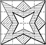
"Divide the square as indicated by the dotted lines, drawing these as full lines in pencil, but do not ink them...The intermediate or section lines must not be drawn with a pencil, but are to be drawn only in ink, the spacing being done by the eye." —Anthony, 1904

Constructing Stars Using Different Shapes

"Divide the square as indicated by the dotted lines, drawing these as full lines in pencil, but do not…
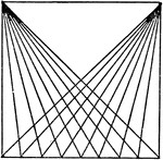
"Use the T square and 45 degree triangle to divide the square as indicated, the size of the small squares being ½". This is an excellent test of precision in measurement and lining. Care must be observed in the inking of this figure to allow each line to dry before inking the next one." —Anthony, 1904

Drawing Diagonal Lines with T Squares and Triangle

"Use the T square and 45 degree triangle to divide the square as indicated, the size of the small squares…
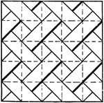
A diagonal line pattern drawing exercise in for T square and triangle. The image is constructed by dividing the paper into squares with the T square, and the diagonal lines are drawn using a 45 degree triangle.

Drawing Exercise for Drawing Diagonal Line Pattern using T Square and Triangle

A diagonal line pattern drawing exercise in for T square and triangle. The image is constructed by dividing…
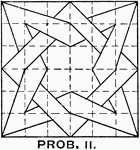
The construction of a star with square overlapping each other using a triangle and T square. This image is drawn by dividing the paper with dashed lines using T square. Using the 45 degree triangle, draw diagonal lines to create the star and the star.

Constructing Star and Box Overlap Pattern using T Square and Triangle

The construction of a star with square overlapping each other using a triangle and T square. This image…
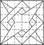
A problem exercise to construct a star overlapping square using a triangle and T square. The image is drawn by dividing the paper with dashed lines using T square. Using the 45 degree triangle, draw diagonal lines to create the star and the star.

Constructing 4 Point Star Overlapping Box Pattern using T Square and Triangle

A problem exercise to construct a star overlapping square using a triangle and T square. The image is…
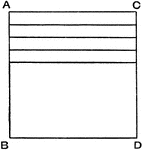
An exercise problem drawing a series of horizontal lines using a straight edge or triangle without using a T square.

Horizontal Solid Line Drawing Exercise

An exercise problem drawing a series of horizontal lines using a straight edge or triangle without using…
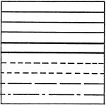
An exercise for mechanical drawing to construct a series of horizontal lines. The solid lines are drawn without using a T square, while the dashed lines are produced using a T square.

Horizontal Solid and Dashed Line Drawing Exercise

An exercise for mechanical drawing to construct a series of horizontal lines. The solid lines are drawn…