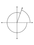
Illustration showing coterminal angles of 70° and -290°. Coterminal angles are angles drawn in standard position that have a common terminal side. In this illustration, neither angle is labeled.

70° and -290° Coterminal Angles

Illustration showing coterminal angles of 70° and -290°. Coterminal angles are angles drawn…
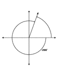
Illustration showing coterminal angles of 70° and -290°. Coterminal angles are angles drawn in standard position that have a common terminal side. In this illustration, only the negative angle is labeled with the proper degree measure.

70° and -290° Coterminal Angles

Illustration showing coterminal angles of 70° and -290°. Coterminal angles are angles drawn…
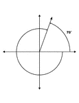
Illustration showing coterminal angles of 70° and -290°. Coterminal angles are angles drawn in standard position that have a common terminal side. In this illustration, only the positive angle is labeled with the proper degree measure.

70° and -290° Coterminal Angles

Illustration showing coterminal angles of 70° and -290°. Coterminal angles are angles drawn…
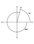
Illustration showing coterminal angles of 75° and -285°. Coterminal angles are angles drawn in standard position that have a common terminal side. In this illustration, both angles are labeled with the proper degree measure.

75° and -285° Coterminal Angles

Illustration showing coterminal angles of 75° and -285°. Coterminal angles are angles drawn…
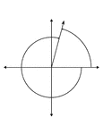
Illustration showing coterminal angles of 75° and -285°. Coterminal angles are angles drawn in standard position that have a common terminal side. In this illustration, neither angle is labeled.

75° and -285° Coterminal Angles

Illustration showing coterminal angles of 75° and -285°. Coterminal angles are angles drawn…
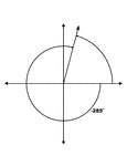
Illustration showing coterminal angles of 75° and -285°. Coterminal angles are angles drawn in standard position that have a common terminal side. In this illustration, only the negative angle is labeled with the proper degree measure.

75° and -285° Coterminal Angles

Illustration showing coterminal angles of 75° and -285°. Coterminal angles are angles drawn…
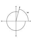
Illustration showing coterminal angles of 75° and -285°. Coterminal angles are angles drawn in standard position that have a common terminal side. In this illustration, only the positive angle is labeled with the proper degree measure.

75° and -285° Coterminal Angles

Illustration showing coterminal angles of 75° and -285°. Coterminal angles are angles drawn…
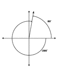
Illustration showing coterminal angles of 80° and -280°. Coterminal angles are angles drawn in standard position that have a common terminal side. In this illustration, both angles are labeled with the proper degree measure.

80° and -280° Coterminal Angles

Illustration showing coterminal angles of 80° and -280°. Coterminal angles are angles drawn…
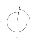
Illustration showing coterminal angles of 80° and -280°. Coterminal angles are angles drawn in standard position that have a common terminal side. In this illustration, neither angle is labeled.

80° and -280° Coterminal Angles

Illustration showing coterminal angles of 80° and -280°. Coterminal angles are angles drawn…
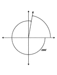
Illustration showing coterminal angles of 80° and -280°. Coterminal angles are angles drawn in standard position that have a common terminal side. In this illustration, only the negative angle is labeled with the proper degree measure.

80° and -280° Coterminal Angles

Illustration showing coterminal angles of 80° and -280°. Coterminal angles are angles drawn…
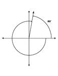
Illustration showing coterminal angles of 80° and -280°. Coterminal angles are angles drawn in standard position that have a common terminal side. In this illustration, only the positive angle is labeled with the proper degree measure.

80° and -280° Coterminal Angles

Illustration showing coterminal angles of 80° and -280°. Coterminal angles are angles drawn…
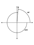
Illustration showing coterminal angles of 85° and -275°. Coterminal angles are angles drawn in standard position that have a common terminal side. In this illustration, both angles are labeled with the proper degree measure.

85° and -275° Coterminal Angles

Illustration showing coterminal angles of 85° and -275°. Coterminal angles are angles drawn…
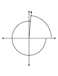
Illustration showing coterminal angles of 85° and -275°. Coterminal angles are angles drawn in standard position that have a common terminal side. In this illustration, neither angle is labeled.

85° and -275° Coterminal Angles

Illustration showing coterminal angles of 85° and -275°. Coterminal angles are angles drawn…
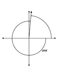
Illustration showing coterminal angles of 85° and -275°. Coterminal angles are angles drawn in standard position that have a common terminal side. In this illustration, only the negative angle is labeled with the proper degree measure.

85° and -275° Coterminal Angles

Illustration showing coterminal angles of 85° and -275°. Coterminal angles are angles drawn…
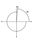
Illustration showing coterminal angles of 85° and -275°. Coterminal angles are angles drawn in standard position that have a common terminal side. In this illustration, only the positive angle is labeled with the proper degree measure.

85° and -275° Coterminal Angles

Illustration showing coterminal angles of 85° and -275°. Coterminal angles are angles drawn…
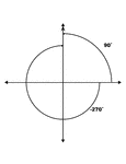
Illustration showing coterminal angles of 90° and -270°. Coterminal angles are angles drawn in standard position that have a common terminal side. In this illustration, both angles are labeled with the proper degree measure.

90° and -270° Coterminal Angles

Illustration showing coterminal angles of 90° and -270°. Coterminal angles are angles drawn…
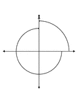
Illustration showing coterminal angles of 90° and -270°. Coterminal angles are angles drawn in standard position that have a common terminal side. In this illustration, neither angle is labeled.

90° and -270° Coterminal Angles

Illustration showing coterminal angles of 90° and -270°. Coterminal angles are angles drawn…
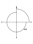
Illustration showing coterminal angles of 90° and -270°. Coterminal angles are angles drawn in standard position that have a common terminal side. In this illustration, only the negative angle is labeled with the proper degree measure.

90° and -270° Coterminal Angles

Illustration showing coterminal angles of 90° and -270°. Coterminal angles are angles drawn…
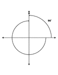
Illustration showing coterminal angles of 90° and -270°. Coterminal angles are angles drawn in standard position that have a common terminal side. In this illustration, only the positive angle is labeled with the proper degree measure.

90° and -270° Coterminal Angles

Illustration showing coterminal angles of 90° and -270°. Coterminal angles are angles drawn…
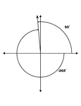
Illustration showing coterminal angles of 95° and -265°. Coterminal angles are angles drawn in standard position that have a common terminal side. In this illustration, both angles are labeled with the proper degree measure.

95° and -265° Coterminal Angles

Illustration showing coterminal angles of 95° and -265°. Coterminal angles are angles drawn…
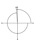
Illustration showing coterminal angles of 95° and -265°. Coterminal angles are angles drawn in standard position that have a common terminal side. In this illustration, neither angle is labeled.

95° and -265° Coterminal Angles

Illustration showing coterminal angles of 95° and -265°. Coterminal angles are angles drawn…
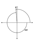
Illustration showing coterminal angles of 95° and -265°. Coterminal angles are angles drawn in standard position that have a common terminal side. In this illustration, only the negative angle is labeled with the proper degree measure.

95° and -265° Coterminal Angles

Illustration showing coterminal angles of 95° and -265°. Coterminal angles are angles drawn…
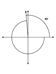
Illustration showing coterminal angles of 95° and -265°. Coterminal angles are angles drawn in standard position that have a common terminal side. In this illustration, only the positive angle is labeled with the proper degree measure.

95° and -265° Coterminal Angles

Illustration showing coterminal angles of 95° and -265°. Coterminal angles are angles drawn…

Illustration showing an angle of depression from a horizontal line to a line of sight.

Angle of Depression

Illustration showing an angle of depression from a horizontal line to a line of sight.

A design of the propeller airplane, or aeroplane, in flight with a higher tail to create an angle of incidence when landing.

Aeroplane High Tail Normal Attitude Design

A design of the propeller airplane, or aeroplane, in flight with a higher tail to create an angle of…

A propeller airplane, or aeroplane, design with a high tail. This design creates a larger angle of incidence for a effective air brake to stop the plane in a shorter distance.

Aeroplane High Tail Slow Landing Design

A propeller airplane, or aeroplane, design with a high tail. This design creates a larger angle of incidence…

Illustration of a propeller aeroplane, or airplane, with lower tail in flight.

Aeroplane Low Tail Design

Illustration of a propeller aeroplane, or airplane, with lower tail in flight.

The propeller airplane, or aeroplane, design in fast landing. This design requires a large landing area to stop the plane.

Aeroplane Low Tail Fast Landing Design

The propeller airplane, or aeroplane, design in fast landing. This design requires a large landing area…
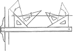
The 45-degree triangle can be used to make a line at a multiple of 15 degrees.

Drawing Lines using Triangle at Angles in Multiples of 15 degrees

The 45-degree triangle can be used to make a line at a multiple of 15 degrees.
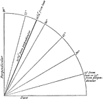
"A quadrant, or one fourth of a circle. The oblique lines indicate various angles with the base. The heavy line indicates the inclination of the earth's axis as compared with the plane of its orbit, which is represented by the base." -Wiswell, 1913

Inclination of Earth's Axis

"A quadrant, or one fourth of a circle. The oblique lines indicate various angles with the base. The…

Illustration showing an angle of elevation from a horizontal line to a line of sight.

Angle of Elevation

Illustration showing an angle of elevation from a horizontal line to a line of sight.
A flashcard featuring an illustration of an angle

Flashcard of an angle

A flashcard featuring an illustration of an angle

A plane flying above land illustrating the use of ailerons to adjust the angle of incidence to adjust the lift. Ailerons are located at the wing tips and controlled by the pilot.

Airplane Flying Above Land

A plane flying above land illustrating the use of ailerons to adjust the angle of incidence to adjust…

An airplane flying above the show illustrating the aerodynamics of the plane with the tail wing at the same angle as the main body. This reduces the lift of the plane by decreasing the angle of incidence.

Airplane Flying Above Shore

An airplane flying above the show illustrating the aerodynamics of the plane with the tail wing at the…
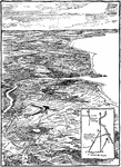
An illustration of the plane flying over land from point A to B by flying the plane with the direction of the plane. Then, flying to point D by creating a diagonal line at 100 mph onto destination point B.

Aeroplane Flying Over Plane

An illustration of the plane flying over land from point A to B by flying the plane with the direction…
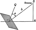
Illustration modeling the illumination on a surface when the surface is not perpendicular to hte rays of light from a source of light.

Illumination of a Surface When the Surface is not Perpendicular to the Source

Illustration modeling the illumination on a surface when the surface is not perpendicular to hte rays…

This image represents an isometric holohedral mirror positioned to produce a cube by reflection.

Isometric Holohedral Mirror

This image represents an isometric holohedral mirror positioned to produce a cube by reflection.

Illustration of a ladder leaning against the side of a building (wall) to form a right triangle .

Ladder Leaning Against a Building

Illustration of a ladder leaning against the side of a building (wall) to form a right triangle .

Illustration of a ladder leaning against a palm tree, that is perpendicular to the ground, to form a right triangle .

Ladder Leaning Against a Tree

Illustration of a ladder leaning against a palm tree, that is perpendicular to the ground, to form a…
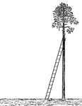
Illustration of a ladder leaning against a palm tree, that is perpendicular to the ground, to form a right triangle .

Ladder Leaning Against a Tree

Illustration of a ladder leaning against a palm tree, that is perpendicular to the ground, to form a…
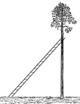
Illustration of a ladder leaning against a palm tree, that is perpendicular to the ground, to form a right triangle .

Ladder Leaning Against a Tree

Illustration of a ladder leaning against a palm tree, that is perpendicular to the ground, to form a…
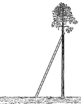
Illustration of a ladder leaning against a palm tree, that is perpendicular to the ground, to form a right triangle .

Ladder Leaning Against a Tree

Illustration of a ladder leaning against a palm tree, that is perpendicular to the ground, to form a…

Illustration of 2 ladders leaning against opposite sides of a palm tree to form similar right triangles. The angles of elevation from the ground to where the ladders meet the tree are congruent. Illustration can be used for problems involving proportions.

2 Ladders Leaning Against a Tree

Illustration of 2 ladders leaning against opposite sides of a palm tree to form similar right triangles.…
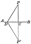
Illustration showing that the perpendicular is the shortest line that can be drawn to a straight line from an external point.

Perpendicular Line Drawn To a Given Line From an External Point

Illustration showing that the perpendicular is the shortest line that can be drawn to a straight line…

Illustration of two lines intersecting at a point. This can be used to show vertical angles.

Intersecting Straight Lines

Illustration of two lines intersecting at a point. This can be used to show vertical angles.
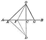
Illustration showing two straight lines drawn from the same point in a perpendicular to a given line, cutting off on the line unequal segments from the foot of the perpendicular, the more remote is the greater.

Lines Drawn From the Same Point in a Perpendicular to a Given line, Cutting Off Segments

Illustration showing two straight lines drawn from the same point in a perpendicular to a given line,…

Illustration showing two lines CA and CB drawn from the point C to the extremities of the straight line AB. OA and OB are two lines similarly drawn, but included by CA and CB. This can be used to show the theorem: The sum of two lines drawn from a point to the extremities of a straight line is greater than the sum of two other lines similarly drawn, but included by them.

Lines Drawn From the Point C to the Extremities of the Straight line AB

Illustration showing two lines CA and CB drawn from the point C to the extremities of the straight line…
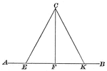
Illustration of two straight lines drawn from a point in a perpendicular to a given line, cutting off on the given line equal segments from the foot of the perpendicular, are equal and make equal angles with the perpendicular. This illustration can be used to show the proof.

Lines Drawn to Another Line to Form Triangle

Illustration of two straight lines drawn from a point in a perpendicular to a given line, cutting off…
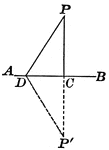
Illustration showing only one perpendicular can be drawn to a given line from a given external point.
Perpendicular Line Drawn to a Given Line from an External Point

Illustration showing only one perpendicular can be drawn to a given line from a given external point.

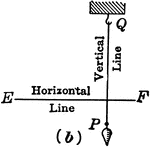
Right angle at perpendicular lines demonstrated by string on plumb line.

Perpendicular Lines

Right angle at perpendicular lines demonstrated by string on plumb line.

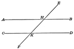
Illustration showing that when two parallel lines are cut by a transversal, the exterior-interior angles are equal.

Parallel Lines Cut By A Transversal

Illustration showing that when two parallel lines are cut by a transversal, the exterior-interior angles…
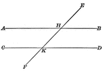
Illustration showing that when two parallel lines are cut by a transversal, the two interior angles on the same side of the transversal are supplementary.

Parallel Lines Cut By A Transversal

Illustration showing that when two parallel lines are cut by a transversal, the two interior angles…

Parallelogram with angles labeled.

Parallelogram

Parallelogram with angles labeled.

Illustration used to show how to draw a parallelogram when given the sides and one of the angles.

Construction Of Parallelogram

Illustration used to show how to draw a parallelogram when given the sides and one of the angles.

Illustration to show that when lines from two opposite vertices of a parallelogram to the midpoints of the opposite sides are drawn, they trisect the diagonal.

Parallelogram With Lines From opposite Vertices to Midpoints

Illustration to show that when lines from two opposite vertices of a parallelogram to the midpoints…
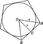
Illustration showing a circle inscribed in a regular pentagon. Or, a regular pentagon circumscribed about a circle.

Regular Pentagon With Circle Inscribed

Illustration showing a circle inscribed in a regular pentagon. Or, a regular pentagon circumscribed…
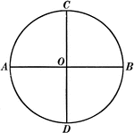
Illustration of a circle with center O and diameters AB and CD perpendicular to each other.

Circle With 2 Perpendicular Diameters

Illustration of a circle with center O and diameters AB and CD perpendicular to each other.
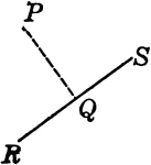
A perpendicular line drawn from point P to straight line RS.

Perpendicular Line Drawn From Point P to Line RS

A perpendicular line drawn from point P to straight line RS.

"The effect of holding polarizing lenses at right angles to each other." -Avery 1895

Polarization of Light

"The effect of holding polarizing lenses at right angles to each other." -Avery 1895

Illustration showing two prisms are equal if the three faces which include a trihedral angle of the one are respectively equal to three faces which include a trihedral angle of the other, and are similarly placed.

Equal Prisms

Illustration showing two prisms are equal if the three faces which include a trihedral angle of the…